A digital microscope system is more than a microscope with a camera attached.
For the system to work well, the microscope optics, camera sensor, adapter, interface, display and software must all be matched to the application.
A high-resolution camera connected to the wrong adapter can produce a narrow field of view.
A 4K camera connected to a 1080p monitor cannot deliver the full benefit of native 4K viewing.
A powerful scientific camera may be unnecessary for routine PCB inspection, while a general-purpose HDMI camera may not provide the sensitivity required for weak fluorescence imaging.
The best results come from treating digital microscopy as a complete imaging system:
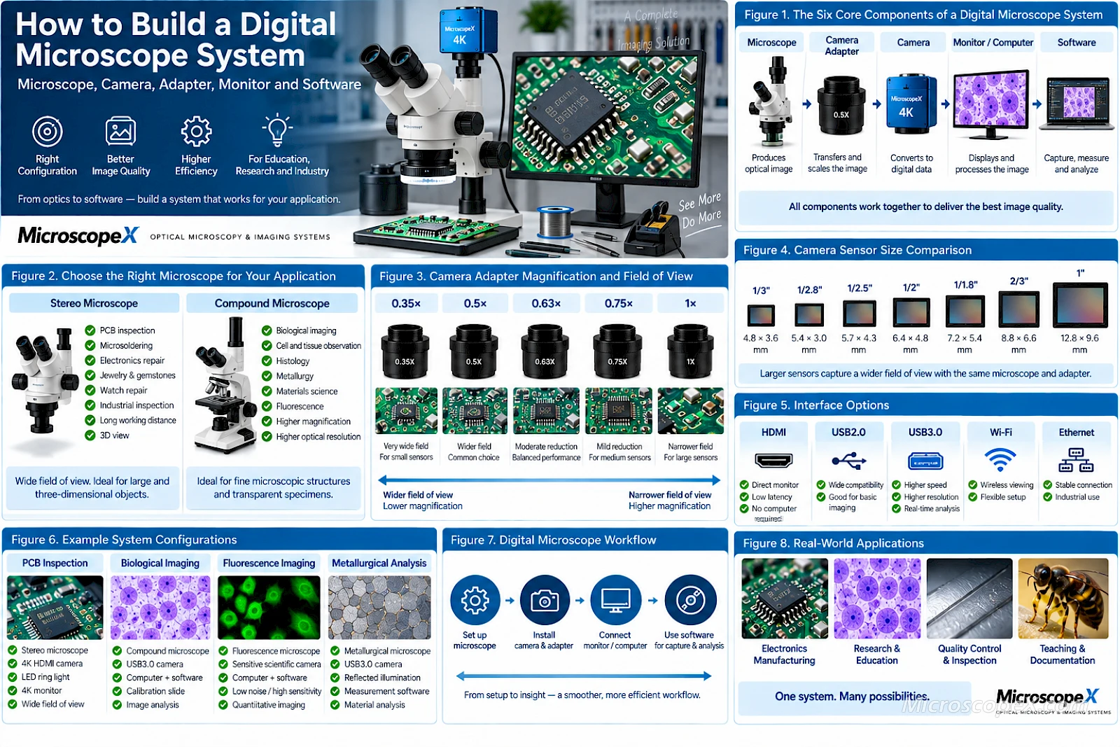
Specimen → Microscope Optics → Camera Adapter → Camera Sensor → Interface → Monitor or Computer → Software
This guide explains how to select each part and build a digital microscope system for biological imaging, electronics inspection, industrial measurement, teaching and scientific applications.
You can also explore the complete range of Microscope Cameras available from MicroscopeX.
What Is a Digital Microscope System?
A digital microscope system combines optical microscopy with electronic image capture and display.
Depending on the application, the system may include:
- A microscope
- Objective lenses
- A trinocular imaging port
- A C-mount or other camera adapter
- A digital microscope camera
- HDMI, USB, USB3.0, Wi-Fi or Ethernet connectivity
- A monitor or computer
- Imaging and measurement software
- Illumination
- Calibration tools
Some digital microscope systems are designed primarily for direct monitor viewing.
Others are optimized for computer-based image acquisition and analysis.
More advanced systems may combine both.
The Six Core Components of a Digital Microscope System
A practical digital microscope system can be divided into six major parts:
| Component | Main Function |
|---|---|
| Microscope | Produces the optical image |
| Objective / Zoom Optics | Determines magnification and optical resolution |
| Camera Adapter | Transfers and scales the image to the sensor |
| Camera | Converts the optical image into digital data |
| Monitor / Computer | Displays and processes the image |
| Software | Capture, measurement, documentation and analysis |
A weakness in any one component can limit the performance of the entire system.
1. Start with the Microscope
The microscope should normally be selected before the camera.
This is because the microscope determines:
- What specimens can be observed
- Optical magnification
- Resolution
- Working distance
- Field of view
- Illumination technique
- Camera-port configuration
The first question is therefore:
What type of microscope does your application require?
Stereo Microscope
A Stereo Microscope is ideal for relatively large, three-dimensional or opaque objects.
Typical applications include:
- PCB inspection
- Microsoldering
- Electronics repair
- Mechanical inspection
- Jewelry
- Gemstones
- Watch repair
- Entomology
- Dissection
- Assembly
- Quality control
Stereo microscopes provide:
- Long working distance
- Wide field of view
- Depth perception
- Space for tools
- Low- to medium-magnification observation
They are particularly suitable for digital industrial inspection.
Compound Microscope
A Compound Microscope is designed for higher-resolution observation of fine microscopic structures.
Typical applications include:
- Cells
- Tissue sections
- Microorganisms
- Histology
- Metallurgy
- Semiconductor structures
- Materials science
- Fluorescence microscopy
Compound microscopes generally provide higher optical magnification and numerical aperture than stereo microscopes.
The correct camera configuration depends heavily on the objective magnification and imaging technique.
2. Choose Binocular or Trinocular
If digital imaging is an important part of the system, a trinocular microscope is usually the most convenient choice.
A binocular microscope has two observation tubes.
A trinocular microscope adds a dedicated third optical path or photo port for a camera.
A typical configuration becomes:
Eyepieces + Camera Port
This allows you to maintain direct optical observation while keeping a digital camera permanently installed.
Why Trinocular Is Better for Digital Imaging
A trinocular system can provide:
- Permanent camera installation
- Easier camera alignment
- Better mechanical stability
- Dedicated camera adapters
- Faster switching between optical and digital observation
- Better suitability for documentation
- Measurement
- Teaching
- Industrial inspection
A binocular microscope can still be converted for camera use through an eyepiece adapter, but this is generally less convenient for a permanent imaging workstation.
3. Define the Application Before Choosing the Camera
The correct microscope camera depends on what you intend to do.
Do not begin with megapixels.
Begin with the application.
PCB Inspection and Electronics
Prioritize:
- Low latency
- Smooth live video
- Large field of view
- HDMI output
- 30–60 FPS or higher
- Good color
- 4K where useful
- Long microscope working distance
A stereo microscope combined with an HDMI camera is a common solution.
Microsoldering
Prioritize:
- Very low latency
- High frame rate
- Comfortable monitor viewing
- Wide field of view
- Good depth perception if using eyepieces
- Stable stand
A camera capable of:
4K for inspection
and:
1080p 60 FPS or higher for live soldering
can provide excellent flexibility.
Biological Imaging
Prioritize:
- Good color reproduction
- Appropriate resolution
- Dynamic range
- Sensor size
- Software
- Image capture
- Measurement
USB or USB3.0 cameras are commonly useful because images can be recorded and analyzed directly on a computer.
Fluorescence Microscopy
Prioritize:
- Sensitivity
- Quantum efficiency
- Low read noise
- Low dark current
- Long exposure capability
- Cooling where required
- Monochrome imaging where appropriate
In this application, a high megapixel count or 4K HDMI output may be much less important than sensitivity.
Industrial Measurement
Prioritize:
- Stable optical geometry
- Calibration
- Resolution
- USB3.0
- Measurement software
- Repeatability
- Low distortion
The camera, microscope and software must operate as a calibrated system.
Education and Teaching
Prioritize:
- Easy setup
- HDMI display
- Large-screen viewing
- Good color
- Image capture
- Simple controls
A standalone camera connected directly to a monitor can be particularly convenient.
4. Choose the Camera Sensor
Once the application is clear, evaluate the sensor.
Important sensor specifications include:
- Sensor size
- Pixel size
- Resolution
- Frame rate
- Dynamic range
- Sensitivity
- Read noise
- Color or monochrome architecture
These specifications interact with one another.
Sensor Size
Common microscope-camera sensor formats include:
- 1/3"
- 1/2.8"
- 1/2.5"
- 1/2"
- 1/1.8"
- 2/3"
- 1"
Sensor size affects how much of the microscope image is captured.
With the same microscope and adapter:
Larger sensor → wider captured field
Smaller sensor → narrower captured field
This makes sensor size particularly important for stereo microscopy and low-magnification inspection.
Pixel Size
Each sensor consists of individual photosensitive pixels.
Larger pixels generally have more physical area available to collect light.
Smaller pixels allow more pixels to fit within the same sensor area.
This creates a balance between:
- Spatial sampling
- Sensitivity
- Resolution
- Noise
- Sensor size
There is no universally ideal pixel size.
The correct pixel size depends on the microscope's optical resolution and application.
Camera Resolution
Common resolutions may include:
- 2 MP
- 5 MP
- 8 MP
- 12 MP
- 20 MP
- Higher resolutions
Higher resolution provides more digital pixels, but it does not automatically increase optical detail.
The microscope must first resolve the information.
The goal is to provide enough digital sampling for the optical image without relying on excessive empty resolution.
1080p vs 4K
For live digital microscopy:
1080p = 1920 × 1080
4K UHD = 3840 × 2160
4K contains approximately four times as many display pixels.
It can be especially useful for:
- PCB inspection
- Large monitors
- Jewelry
- Teaching
- Documentation
- Digital cropping
1080p remains highly useful where:
- High FPS matters
- Low latency matters
- Bandwidth is limited
- 4K display is unnecessary
5. Match the Camera Adapter
The camera adapter is one of the most frequently overlooked components of a digital microscope system.
For a C-mount camera, the optical chain often looks like:
Microscope → Trinocular Port → C-Mount Adapter → Camera
The adapter determines how the microscope image is projected onto the sensor.
Common Adapter Magnifications
Camera adapters may use reduction factors such as:
- 0.35×
- 0.5×
- 0.63×
- 0.75×
- 1×
A lower adapter factor generally projects a wider field onto the sensor.
For example:
0.5× adapter → wider camera field
1× adapter → narrower camera field
But the correct adapter must match the microscope and sensor.
Small Sensor + High Adapter Magnification
This combination often produces:
- Narrow field of view
- Strong crop
- Camera view much smaller than eyepiece view
Small Sensor + Reduction Adapter
A suitable reduction adapter can provide:
- Wider field of view
- Better use of the sensor
- More natural digital observation
Large Sensor + Incorrect Adapter
A large sensor can expose limitations in the optical image circle.
Possible problems include:
- Vignetting
- Dark corners
- Poor edge sharpness
- Uneven illumination
The adapter therefore needs to be matched to the sensor rather than selected independently.
MicroscopeX offers several dedicated TV and C-mount adapter systems, including the NIKON TV Adapter.
6. Check the Camera Mount
C-mount is one of the most common standards for professional microscope cameras.
A typical C-mount interface uses:
- 1-inch diameter
- 32 threads per inch
- Approximately 17.526 mm flange focal distance
Many USB, HDMI and scientific microscope cameras use this interface.
You can browse compatible C-Mount Cameras.
What If the Microscope Does Not Have a Trinocular Port?
A camera may still be installed through an eyepiece tube.
Typical microscope eyepiece tube diameters include:
- 23.2 mm
- 30 mm
- 30.5 mm
Adapters can convert between these tube sizes and a camera interface.
See Microscope Eyepiece Converters for examples of this type of accessory.
For frequent professional imaging, however, a dedicated trinocular camera port is usually more convenient.
7. Choose the Camera Interface
The camera sensor captures the image.
The interface determines how that data reaches the display or computer.
Common interfaces include:
- HDMI
- USB2.0
- USB3.0
- Wi-Fi
- Ethernet
- Multi-interface systems
Each is suitable for different workflows.
HDMI
HDMI is ideal for direct monitor viewing.
Typical configuration:
Microscope → HDMI Camera → Monitor
Advantages:
- No computer required
- Simple setup
- Low-latency viewing
- Excellent for inspection
- Good for teaching
- Suitable for microsoldering
HDMI is especially attractive for industrial workstations.
USB
USB cameras connect to a computer.
Typical configuration:
Microscope → USB Camera → Computer → Imaging Software
Advantages:
- Image capture
- Video recording
- Measurement
- Annotation
- Analysis
- File storage
- Software control
USB cameras are particularly useful for biological imaging and documentation.
USB3.0
USB3.0 offers greater bandwidth than USB2.0.
This is useful for:
- Higher resolution
- Larger sensors
- Higher FPS
- Faster image transfer
- Real-time analysis
The U3CMOS Series provides C-mount USB3.0 microscope camera configurations for image capture and analysis.
Wi-Fi
Wi-Fi provides wireless image transmission.
Advantages include:
- Flexible device placement
- Tablet viewing
- Reduced cabling
- Classroom sharing
However, wireless connections may introduce more latency than a direct wired interface.
For precision live manipulation, HDMI or USB may therefore be preferable.
Ethernet
Ethernet can be useful for:
- Longer cable runs
- Network integration
- Industrial installations
- Remote imaging
- Machine vision
Network cameras can be particularly useful where the microscope is part of a larger inspection system.
Multi-Interface Cameras
Some microscope cameras support combinations such as:
- HDMI + USB
- HDMI + USB3.0
- HDMI + Wi-Fi
- HDMI + Ethernet
- HDMI + USB + Ethernet
These cameras can provide excellent flexibility.
For example:
HDMI → Large monitor for live viewing
while:
USB → Computer for image capture and measurement
This allows a single camera to support multiple workflows.
8. Choose the Monitor
The monitor is an important part of the imaging system, especially when the operator works primarily from the screen.
Important factors include:
- Resolution
- Screen size
- Refresh rate
- Color reproduction
- Viewing angle
- Input latency
- HDMI compatibility
1080p Monitor
A 1080p monitor provides:
1920 × 1080 pixels
Advantages:
- Affordable
- Widely compatible
- Good for general microscopy
- Suitable for high-frame-rate operation
For many electronics applications, a good 1080p 60 Hz monitor remains highly practical.
4K Monitor
A 4K monitor provides:
3840 × 2160 pixels
Advantages:
- More display detail
- Better large-screen image quality
- Excellent for PCB inspection
- Better for teaching
- More workspace for software
- Useful for high-resolution cameras
To fully benefit from native 4K camera output, the monitor must also support 4K input at the required frame rate.
Monitor Size
Common workstation sizes include:
- 21.5"
- 24"
- 27"
- 32"
A larger monitor can provide more comfortable inspection, but larger is not automatically better.
Consider:
- Viewing distance
- Desk size
- Microscope position
- Pixel density
For a close workstation, a high-resolution 27" or 32" display can provide an excellent balance.
Monitor Latency
For static imaging, monitor latency is usually not critical.
For microsoldering, it can be.
The total delay may come from:
Camera processing + interface + monitor processing
Even a high-FPS camera can feel slow if the display introduces significant delay.
For screen-based hand work, choose a monitor with low input latency.
9. Choose the Computer
If the camera uses USB or USB3.0, computer performance becomes part of the imaging chain.
Important resources include:
- CPU
- RAM
- USB bandwidth
- GPU where required
- Storage speed
- Storage capacity
- Display resolution
A high-resolution camera generating large image files requires more computer resources than a basic 2 MP system.
Storage Requirements
High-resolution images and video can consume considerable storage.
4K video requires significantly more data than 1080p when similar compression settings are used.
For documentation-heavy workflows, consider:
- SSD storage
- External backup
- Network storage
- File naming
- Archiving procedures
A good digital microscopy workflow includes data management, not just image acquisition.
10. Choose the Imaging Software
Software determines what you can do with the image after it reaches the computer.
Typical functions include:
- Live preview
- Image capture
- Video recording
- Exposure control
- White balance
- Measurement
- Calibration
- Annotation
- Image processing
- Extended depth of field
- Stitching
- Reporting
- Data export
MicroscopeX provides microscope camera software and drivers through the Software & Drivers section.
ImageView
For compatible MicroscopeX camera families, ImageView provides a computer-based imaging environment for camera operation and image processing.
The current software package can be found under:
Software compatibility should always be checked against the specific camera model and operating system.
11. Calibration for Measurement
If the microscope will be used for dimensional measurement, the imaging system should be calibrated.
Calibration establishes the relationship between:
Image pixels
and:
Real specimen dimensions
For example:
1 pixel = X µm
The exact value depends on:
- Objective magnification
- Zoom setting
- Camera sensor
- Adapter magnification
- Image resolution
Calibration Slides
A stage micrometer or calibration slide provides a known dimensional reference.
The software uses this reference to establish the scale.
After calibration, measurements may include:
- Distance
- Diameter
- Radius
- Angle
- Area
- Perimeter
Different microscope magnifications normally require separate calibration values.
Never Assume Calibration Remains Valid After Changing Magnification
If you change:
- Objective
- Zoom
- Adapter
- Camera resolution
- Optical configuration
the calibration may need to be updated.
For accurate industrial measurement, calibration should be treated as part of the workflow rather than a one-time setup.
12. Choose the Correct Illumination
Digital image quality depends strongly on illumination.
A better camera cannot compensate for badly illuminated specimens.
Different microscopy applications require different lighting.
Stereo Microscope Illumination
Common options include:
LED Ring Light
Suitable for:
- PCB inspection
- Electronics
- General industrial work
- Jewelry
Provides relatively uniform illumination.
Gooseneck Lighting
Useful for:
- Surface texture
- Directional shadows
- Defect inspection
Polarized Lighting
Useful for reducing reflections from:
- Metals
- Solder
- Reflective surfaces
Coaxial Illumination
Useful for:
- Flat reflective surfaces
- Semiconductor inspection
- Certain industrial applications
Compound Microscope Illumination
Depending on the microscope, techniques may include:
- Brightfield
- Darkfield
- Phase contrast
- Fluorescence
- Polarized light
- Reflected illumination
The camera must have sufficient sensitivity and dynamic range for the selected technique.
Building a Digital Stereo Microscope System
A common industrial setup may look like:
Stereo Microscope
↓
Trinocular Camera Port
↓
C-Mount Adapter
↓
HDMI / USB Camera
↓
Monitor + Computer
This can provide both:
- Direct optical stereo observation
- Digital imaging
Such systems are particularly useful for:
- Electronics
- PCB repair
- Jewelry
- Inspection
- Manufacturing
- Training
Example: PCB Inspection System
A practical PCB inspection system might include:
Microscope
Continuous zoom Stereo Microscope
Stand
Stable boom stand
Illumination
Adjustable LED ring light
Camera
4K HDMI + USB camera
Adapter
Sensor-matched C-mount adapter
Display
27" or 32" 4K monitor
Software
Image capture and measurement software
Optional Accessories
- PCB holder
- Calibration slide
- Polarized illumination
- Directional light
Example: Microsoldering System
For active microsoldering, priorities change slightly.
Recommended configuration:
- Stereo microscope
- Long working distance
- 0.5× auxiliary objective where appropriate
- Boom stand
- LED ring light
- Trinocular head
- HDMI camera
- High-frame-rate 1080p mode
- Low-latency monitor
Use:
4K mode for detailed inspection
and:
60 FPS or higher mode for live manipulation
where supported.
Building a Digital Biological Microscope System
A typical biological system might include:
↓
Trinocular Port
↓
C-Mount Adapter
↓
USB3.0 Camera
↓
Computer
↓
Imaging Software
This configuration supports:
- Observation
- Image capture
- Documentation
- Measurement
- Teaching
- Analysis
Example: Routine Biological Imaging
Recommended configuration:
Microscope
Trinocular biological Compound Microscope
Objectives
4× / 10× / 40× / 100×
depending on application
Camera
Color CMOS USB3.0 camera
Adapter
Sensor-matched C-mount adapter
Computer
USB3.0 compatible workstation
Software
Image capture and measurement software
Building a Fluorescence Imaging System
Fluorescence imaging places much greater demands on the camera.
Typical configuration:
↓
Trinocular Imaging Port
↓
Optical Adapter
↓
Sensitive Scientific Camera
↓
Computer
↓
Scientific Imaging Software
Camera priorities include:
- High quantum efficiency
- Low read noise
- Low dark current
- Long exposure
- Cooling
- High dynamic range
For weak fluorescence, these specifications are generally more important than HDMI resolution.
Building a Digital Metallurgical Microscope System
Metallurgical imaging is commonly used for:
- Metal surfaces
- Grain structures
- Coatings
- Semiconductor samples
- Polished materials
- Industrial defects
A useful configuration includes:
- Metallurgical compound microscope
- Reflected-light illumination
- Trinocular port
- USB3.0 camera
- C-mount adapter
- Measurement software
- Calibration slide
For measurement and quality control, optical geometry and calibration are particularly important.
How to Match the Complete System
A well-designed digital microscope should be considered from both directions.
Optical Side
Ask:
- What specimen?
- What magnification?
- What resolution?
- What working distance?
- What illumination?
Digital Side
Ask:
- What sensor size?
- What pixel size?
- What resolution?
- What FPS?
- What interface?
- What display?
- What software?
The two sides meet at the camera adapter.
Example of a Poorly Matched System
Imagine:
- Excellent stereo microscope
- Small camera sensor
- 1× C-mount adapter
- 4K camera
- 1080p monitor
Possible result:
- Narrow camera field
- 4K advantage wasted on the display
- High specification numbers but poor usability
Example of a Better-Matched System
Instead:
- Excellent stereo microscope
- Appropriately sized sensor
- Correct reduction adapter
- 4K / high-FPS camera
- 4K low-latency monitor
Result:
- Wider field
- Better display detail
- Comfortable inspection
- More effective use of the camera
System matching matters more than buying the most expensive individual component.
Common Digital Microscope System Mistakes
Mistake 1: Choosing the Camera First
Choose the microscope and application first.
Then select the camera.
Mistake 2: Buying Based Only on Megapixels
Megapixels do not tell you:
- Sensor size
- Pixel size
- Sensitivity
- FPS
- Dynamic range
- Field of view
Mistake 3: Ignoring the Camera Adapter
The adapter affects:
- Field of view
- Image magnification
- Sensor coverage
- Parfocality
It is part of the optical system.
Mistake 4: Buying a 4K Camera Without a 4K Display
You may still capture high-resolution images, but you will not see the full native 4K live output on a 1080p monitor.
Mistake 5: Ignoring Frame Rate
For live work, FPS can be more important than maximum resolution.
Mistake 6: Ignoring Latency
For microsoldering and manipulation, low latency is essential.
Mistake 7: Ignoring Sensor Size
A high-resolution small sensor may still provide a narrow camera field.
Mistake 8: Using the Wrong Interface
HDMI is excellent for direct viewing.
USB is excellent for computer imaging.
Choose according to workflow.
Mistake 9: Ignoring Software Before Buying
Check:
- Operating-system compatibility
- Camera support
- Measurement features
- Driver availability
before purchasing.
Mistake 10: Ignoring Illumination
Poor illumination can limit image quality more than camera resolution.
Digital Microscope System Selection Table
| Application | Microscope | Camera Priority | Interface | Display |
|---|---|---|---|---|
| PCB Inspection | Stereo | Resolution + FPS | HDMI | 4K monitor |
| Microsoldering | Stereo | Low latency + FPS | HDMI | Low-latency monitor |
| Biological Imaging | Compound | Color + resolution | USB3.0 | Computer |
| Fluorescence | Compound | Sensitivity + low noise | USB3.0 | Computer |
| Industrial Measurement | Stereo / Compound | Resolution + calibration | USB3.0 | Computer |
| Teaching | Stereo / Compound | Simplicity + display | HDMI | Large monitor |
| Jewelry | Stereo | Color + detail | HDMI | 4K monitor |
| Documentation | Stereo / Compound | Resolution + software | USB3.0 | Computer |
A Step-by-Step Digital Microscope Buying Checklist
Before ordering the system, answer these questions.
Step 1 — What is the specimen?
Examples:
- PCB
- Cells
- Tissue
- Metal
- Jewelry
- Semiconductor
- Insect
Step 2 — What microscope type is required?
Choose:
- Stereo
- Biological
- Metallurgical
- Fluorescence
- Polarizing
- Inverted
Step 3 — What magnification and resolution are required?
Do not buy more magnification than the application needs.
Step 4 — Do you need direct optical observation?
If yes, consider binocular or trinocular viewing.
For camera integration, trinocular is usually preferable.
Step 5 — What sensor size is appropriate?
Match sensor dimensions to:
- Microscope image circle
- Adapter
- Desired field of view
Step 6 — How much resolution do you need?
Consider:
- Live viewing
- Still images
- Documentation
- Cropping
Step 7 — How much FPS do you need?
For static imaging:
30 FPS may be sufficient.
For manipulation:
60 FPS or higher may be preferable.
Step 8 — HDMI or USB?
Choose HDMI for:
- Standalone viewing
- Low latency
- Inspection
Choose USB for:
- Measurement
- Capture
- Analysis
Choose both if both workflows matter.
Step 9 — What adapter is required?
Confirm:
- Camera mount
- Microscope photo port
- Sensor size
- Reduction factor
- Parfocality
Step 10 — What display is required?
Match:
- Camera resolution
- Output format
- Monitor resolution
- Refresh rate
Step 11 — What software is required?
Confirm:
- Driver compatibility
- Image capture
- Measurement
- Calibration
- Analysis
Step 12 — Do you need calibration?
If performing measurements:
Yes.
Include a calibration slide in the system.
Frequently Asked Questions
What do I need to connect a camera to a microscope?
For a typical trinocular system you need:
- Microscope
- Camera port
- Compatible camera adapter
- Digital camera
- HDMI monitor or computer
The exact adapter depends on the microscope and camera sensor.
Can any microscope be converted to digital?
Many microscopes can be equipped with cameras.
A trinocular microscope is easiest.
Binocular microscopes may require an eyepiece camera or C-mount-to-eyepiece adapter.
Compatibility should be checked before purchasing.
Is a trinocular microscope necessary?
No, but it is strongly recommended when digital imaging is an important part of the workflow.
It provides a dedicated camera port without sacrificing both observation eyepieces.
What is the best camera for a digital microscope?
There is no universal best camera.
For PCB inspection, prioritize FPS and low latency.
For biological microscopy, prioritize color, sensor performance and software.
For fluorescence, prioritize sensitivity and noise.
Should I choose HDMI or USB?
Choose HDMI for direct monitor viewing.
Choose USB for computer-based capture, measurement and analysis.
Multi-interface cameras can provide both.
Do I need a C-mount adapter?
If the camera uses C-mount and the microscope does not provide a directly compatible C-mount imaging port, yes.
The adapter must also be optically matched to the sensor.
Why does my camera show less than the eyepieces?
The camera sensor and adapter may capture only the center of the microscope image.
A suitable reduction adapter or larger sensor may provide a wider field.
Is 4K necessary?
No.
4K is especially useful for:
- Large-screen viewing
- PCB inspection
- Teaching
- Documentation
- Cropping
1080p remains excellent for many applications and can provide higher frame rates.
Can I use a television instead of a monitor?
If the camera provides a compatible HDMI output, many HDMI televisions can display the image.
However, for precision work, check:
- Input latency
- Resolution
- Refresh rate
- Image processing
A computer monitor may provide more predictable performance.
Do I need a computer?
Not for a standalone HDMI microscope system.
A computer becomes important when you need:
- Measurement
- Advanced capture
- Analysis
- Image processing
- File management
What software can I use with MicroscopeX cameras?
Compatible camera software and drivers are available through the Software & Drivers section.
Specific camera compatibility should be checked before installation.
Conclusion
Building a digital microscope system is not simply a matter of attaching the highest-resolution camera you can find.
The best system is created by matching:
Microscope
Objective or Zoom Optics
Camera Adapter
Sensor
Interface
Monitor or Computer
Software
Illumination
For electronics and PCB inspection, prioritize working distance, field of view, frame rate and low latency.
For biological imaging, prioritize optical resolution, sensor quality, color and software.
For fluorescence, sensitivity and low noise become critical.
For industrial measurement, calibration and system stability matter most.
The key principle is simple:
Treat the microscope, camera, adapter and digital workflow as one imaging system — not as separate products.
A correctly matched system will usually provide better results than a collection of individually impressive specifications that were never designed to work together.
Build Your Digital Microscope System
Explore MicroscopeX imaging components:
- Stereo Microscopes
- Compound Microscopes
- Microscope Cameras
- C-Mount Cameras
- U3CMOS USB3.0 Cameras
- Microscope Eyepiece Converters
- NIKON TV Adapter
- Software & Drivers
- ImageView Software & Driver
Need help matching the microscope, camera, adapter, display and software?
Contact MicroscopeX for complete digital microscopy system configuration support.