If you are connecting a digital camera to a microscope, there is a good chance you will encounter the term C-mount.
C-mount is one of the most widely used mechanical interfaces for microscope cameras, industrial cameras, machine-vision systems, and scientific imaging equipment.
At first, it appears simple:
Microscope → C-mount adapter → C-mount camera
But choosing a compatible system involves more than checking whether the threads fit.
A camera may mechanically attach to a microscope and still produce:
A field of view that is too narrow
Dark corners or vignetting
Poor optical coverage
Excessive image magnification
Reduced image quality
Difficulty achieving parfocality
A camera view very different from the eyepiece view
The reason is that a microscope-camera system must match three different elements:
Mechanical interface + optical adapter + camera sensor
This guide explains what C-mount means, how microscope camera adapters work, how sensor size affects field of view, and how to select the correct camera and adapter combination.
You can also browse the full range of C-mount microscope cameras available from MicroscopeX.
What Is a C-Mount?
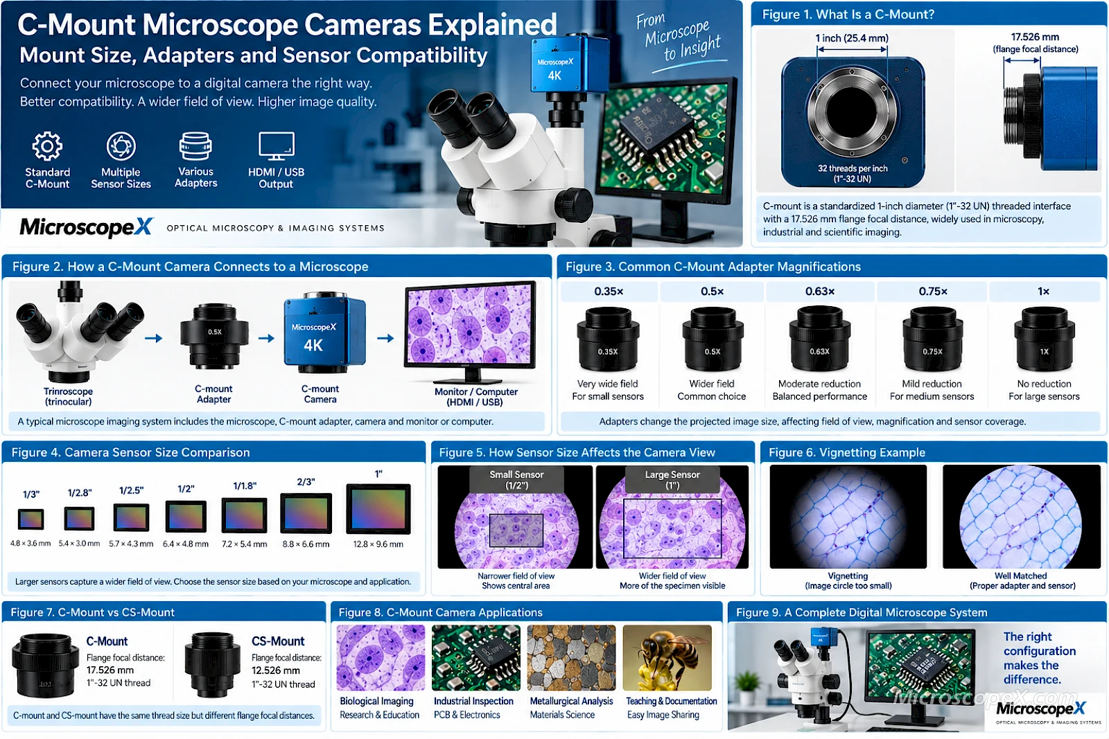
C-mount is a standardized threaded camera interface.
The traditional C-mount specification uses:
1-inch diameter
with:
32 threads per inch
It also defines a flange focal distance of approximately:
17.526 mm
The standardized mechanical interface makes it possible to connect many different cameras, lenses, adapters, microscopes, and imaging systems.
In microscopy, C-mount is particularly common on:
Scientific cameras
CMOS microscope cameras
Industrial inspection cameras
Machine-vision cameras
MicroscopeX offers a wide range of microscope cameras using C-mount and other microscope imaging interfaces.
What Does “C-Mount Camera” Actually Mean?
When a microscope camera is described as a C-mount camera, it usually means that the front of the camera has the standardized C-mount threaded interface.
It does not mean that the camera can automatically be connected correctly to every microscope.
The microscope must provide a compatible optical output.
This may be achieved through:
A dedicated trinocular camera port
A microscope photo tube
A C-mount photo adapter
A reduction lens adapter
An eyepiece-tube adapter
Therefore, mechanical compatibility and optical compatibility are two different questions.
Mechanical Compatibility vs Optical Compatibility
This distinction is essential.
Mechanical Compatibility
Mechanical compatibility asks:
Can the camera physically attach to the adapter?
If both components use standard C-mount threads, the answer may be yes.
Optical Compatibility
Optical compatibility asks:
Will the microscope image correctly fill the sensor and remain properly focused?
This depends on:
Microscope optical design
Camera sensor size
Adapter magnification
Image circle
Camera port design
Relay optics
Parfocal adjustment
A mechanically compatible combination can still be optically poor.
That is why selecting a microscope camera should never stop at:
“It has a C-mount, so it fits.”
The Basic C-Mount Microscope Imaging System
A typical trinocular microscope camera system looks like this:
Specimen
↓
Objective
↓
Microscope optical system
↓
Trinocular imaging port
↓
↓
Camera sensor
↓
HDMI monitor or computer
Each component influences the final image.
The camera records only the image delivered to its sensor by the microscope and adapter.
Why Do Microscopes Need a Camera Adapter?
A trinocular microscope does not necessarily project an image with the correct size and geometry for every camera sensor.
The adapter performs the optical and mechanical connection between the microscope and camera.
Depending on the design, an adapter may:
Convert the microscope photo port to C-mount
Reduce image magnification
Match the image circle to the sensor
Maintain parfocality
Position the camera at the correct optical distance
Some adapters are purely mechanical.
Others contain optical elements.
In microscopy, optical C-mount adapters with reduction factors such as 0.35×, 0.5×, 0.63×, 0.75×, or 1× are very common.
What Does 0.5× C-Mount Adapter Mean?
A 0.5× adapter reduces the size of the image projected onto the camera sensor.
This has two major practical effects:
The camera captures a wider field of view
The effective camera magnification is reduced
This is especially useful with smaller sensors.
Suppose the microscope produces an image large enough to cover a broad image circle, but your camera has a relatively small sensor.
Without optical reduction, the sensor may capture only the center of that image.
Using a 0.5× adapter can project a larger portion of the microscope image onto the smaller sensor.
What Does a 1× C-Mount Adapter Mean?
A 1× adapter does not apply the same image reduction as a 0.5× adapter.
The sensor therefore captures a smaller portion of the microscope's available image.
This can produce:
A narrower field of view
Greater effective image magnification on the sensor
A 1× adapter may be appropriate for:
Larger camera sensors
Applications where a narrower field is desired
Optical systems designed specifically for that sensor size
It is not automatically better simply because it has a higher numerical value.
Common Microscope Camera Adapter Magnifications
Typical reduction factors include:
| Adapter | General Effect | Typical Use |
|---|---|---|
| 0.35× | Very wide camera field | Small sensors |
| 0.5× | Wider camera field | Common small/medium sensors |
| 0.63× | Moderate reduction | Medium sensors |
| 0.75× | Mild reduction | Medium/larger sensors |
| 1× | No major reduction | Larger sensors or narrower field |
| 1.2× | Increased projection | Specialized configurations |
The exact best combination depends on the microscope optical system.
Do not choose an adapter based only on this table.
The microscope manufacturer or imaging-system supplier should confirm compatibility.
MicroscopeX, for example, offers microscope camera adapters with multiple reduction factors, including solutions that convert trinocular microscope photo ports to C-mount. See the NIKON TV Adapter as an example of this type of optical interface.
Camera Sensor Size Is the Other Half of the Equation
Once the adapter has projected the microscope image, the camera sensor determines how much of that image is actually recorded.
Common microscope-camera sensor formats include:
1/3"
1/2.8"
1/2.5"
1/2"
1/1.8"
2/3"
1"
Larger sensors physically cover a larger area.
With the same microscope and adapter, a larger sensor generally captures a wider field of view.
A smaller sensor captures a more cropped central region.
Sensor Format Does Not Equal the Actual Sensor Diameter
A common source of confusion is the inch-based sensor format.
For example:
1/2" sensor
does not mean the sensor is physically 12.7 mm wide or diagonal.
These format names come from older imaging conventions.
For actual optical calculations, the more useful specifications are:
Sensor width
Sensor height
Sensor diagonal
Pixel dimensions
When precise field-of-view matching matters, use the actual sensor dimensions rather than relying only on the format name.
How Sensor Size Changes the Camera View
Imagine a circular microscope image being projected toward the camera.
Inside that image circle, place two rectangular sensors.
Small Sensor
The smaller rectangle captures only the center.
Result:
Smaller visible area
Narrower field of view
Apparent stronger crop
Large Sensor
The larger rectangle covers more of the image.
Result:
Wider field of view
More of the specimen visible
Camera view may more closely resemble the eyepiece view
This is why upgrading from a small sensor to a larger sensor can sometimes produce a much more dramatic difference in usability than simply increasing megapixels.
Adapter Magnification and Sensor Size Work Together
Sensor size should never be considered independently from adapter magnification.
For example:
Small Sensor + 1× Adapter
Likely result:
Narrow field of view
Small Sensor + 0.5× Adapter
Likely result:
Wider field of view
Large Sensor + 1× Adapter
Can provide:
Wide field with good sensor coverage
if the microscope image circle supports it.
Large Sensor + Very Strong Reduction
Potential result:
Vignetting or optical limitations
if the adapter cannot correctly illuminate the entire sensor.
The correct configuration is therefore a matching problem.
Why Does My Camera Show Less Than the Eyepieces?
This is one of the most common microscope-camera questions.
You look through the eyepieces and see a large circular field.
Then you look at the monitor and see only a much smaller central area.
The camera is not necessarily malfunctioning.
The difference is usually caused by:
Camera sensor size
C-mount adapter magnification
Microscope camera-port optics
A small camera sensor connected through a 1× adapter often sees a relatively narrow field.
Changing to a suitable reduction adapter can make the camera field considerably wider.
Matching the Camera View to the Eyepiece View
It is often desirable for the camera to capture a field similar to what the operator sees through the eyepieces.
Exact matching is not always possible or necessary.
But a well-matched system should avoid an extreme difference.
The required adapter depends on:
Eyepiece field number
Microscope optical path
Camera sensor dimensions
Intermediate image size
A 0.5× adapter may work very well with one microscope and sensor but be inappropriate for another.
This is why complete system configuration matters.
Example: 1/2" Sensor
Suppose you have a relatively small microscope camera sensor.
With a 1× adapter, the sensor may capture only a narrow central portion of the available image.
Changing to an appropriate 0.5× adapter reduces the projected image.
The smaller sensor can now capture a larger portion of the microscope field.
This is often one of the simplest ways to improve camera field of view.
Example: 1/1.8" Sensor
A 1/1.8" sensor is physically larger than many 1/2.8" or 1/3" sensors.
It may therefore require less optical reduction to achieve a useful field of view.
Depending on the microscope, an adapter around 0.63×, 0.75×, or another appropriate value may provide a good balance.
Again, the exact choice should be based on the actual optical design.
Example: 1" Sensor
A 1" class sensor requires a significantly larger image circle than a small sensor.
This can provide an excellent wide field when the microscope and adapter are designed to support it.
However, attaching a large sensor to an optical system designed for a much smaller image circle can cause:
Dark corners
Reduced edge quality
Uneven illumination
Vignetting
A larger sensor therefore does not automatically guarantee a better result.
The microscope must illuminate it properly.
What Is Vignetting?
Vignetting occurs when the image becomes dark or cut off toward the corners or edges.
In severe cases, the camera may show a bright circular region surrounded by dark corners.
Common causes include:
Sensor larger than the available image circle
Incorrect C-mount adapter
Adapter optics that do not cover the sensor
Incorrect optical spacing
Incompatible microscope photo port
Vignetting is primarily a system-matching problem.
Why a Lower-Magnification Adapter Can Sometimes Cause Vignetting
At first this may seem counterintuitive.
A lower-magnification adapter gives a wider field, which sounds better.
But widening the captured field also requires the optical system to cover more of the sensor.
If the adapter or microscope cannot provide a sufficiently large corrected image circle, the edges may become dark or degraded.
Therefore:
Widest field of view is not always the best field of view.
The goal is to capture the widest well-corrected and evenly illuminated field.
What Is Parfocality?
A camera system is parfocal when the image remains approximately focused when switching between:
Eyepiece observation
Camera observation
For example, you focus the specimen through the eyepieces and then check the monitor.
Ideally, the camera image should also be in focus or require only minimal adjustment.
Poorly configured adapters can produce significant focus differences.
Many dedicated microscope camera adapters include adjustments that help establish proper parfocality.
Why Parfocality Matters
Without parfocality, the workflow becomes frustrating.
You may repeatedly:
Focus through the eyepieces.
Switch to the camera.
Refocus.
Return to the eyepieces.
Refocus again.
This is particularly inconvenient for:
Photography
Documentation
Teaching
Measurement
Quality control
A correctly adjusted imaging system makes switching between direct and digital observation much easier.
C-Mount vs CS-Mount
C-mount and CS-mount look very similar because both use the same basic thread diameter and pitch.
But they have different flange focal distances.
C-Mount
Approximately:
17.526 mm
CS-Mount
Approximately:
12.526 mm
The difference is approximately:
5 mm
This means they should not be treated as identical standards.
A suitable spacer can often allow a C-mount lens to be used on a CS-mount camera.
But the reverse arrangement is generally more problematic because the CS lens would need to sit closer to the sensor than a C-mount camera body normally allows.
For microscope imaging, always confirm whether the camera interface is truly C-mount.
C-Mount vs Eyepiece Cameras
Not all microscope cameras use C-mount.
An eyepiece camera is designed to fit into an eyepiece tube instead of attaching to a dedicated trinocular C-mount port.
Typical eyepiece tube diameters include:
23.2 mm
30 mm
30.5 mm
Eyepiece cameras can be convenient for microscopes that do not have a trinocular photo port.
However, a dedicated trinocular C-mount configuration usually provides greater flexibility for professional imaging.
MicroscopeX also provides eyepiece converters for adapting common microscope tube sizes.
C-Mount vs Eyepiece Camera: Which Is Better?
C-Mount System
Advantages:
Designed for dedicated imaging
Wide camera selection
Easier sensor matching
Multiple adapter magnifications
Suitable for professional imaging
Good for high-resolution cameras
Convenient for permanent installations
Best for:
Trinocular microscopes
Research
Measurement
Professional documentation
Eyepiece Camera
Advantages:
Easy retrofit
Works with many binocular or monocular microscopes
Compact
Simple installation
Best for:
Education
Basic documentation
Existing microscopes without camera ports
Portable use
Neither system is universally better.
The correct choice depends on the microscope.
Trinocular Microscopes and C-Mount Cameras
A trinocular microscope is usually the easiest platform for integrating a professional C-mount camera.
It provides:
Two eyepieces for direct observation
A dedicated third optical port for imaging
This lets the operator observe through the microscope while maintaining a camera connection.
C-mount cameras can be used with both stereo microscopes and compound microscopes when the microscope provides a suitable imaging port and adapter.
C-Mount Cameras for Stereo Microscopes
Stereo microscopes frequently use cameras for:
PCB inspection
Microsoldering
Jewelry
Watch repair
Entomology
Quality control
Training
Important camera considerations include:
Wide field of view
Sensor size
Frame rate
Low latency
HDMI or USB output
Adapter reduction
Because stereo microscopes operate at relatively low magnifications and often show large specimens, field-of-view matching can be especially important.
A poorly matched camera can make the monitor view feel much more magnified and restrictive than the eyepiece view.
C-Mount Cameras for Compound Microscopes
Compound microscopes use C-mount cameras for:
Biological imaging
Histology
Metallurgy
Materials science
Fluorescence
Education
Laboratory documentation
Measurement
At higher optical magnifications, pixel sampling becomes particularly important.
The goal is to choose:
Objective magnification + adapter magnification + pixel size
so that the camera adequately samples the optical information produced by the microscope.
Simply choosing the highest-megapixel camera does not guarantee more useful detail.
C-Mount Cameras for Metallurgical Microscopy
Metallurgical microscopes observe opaque surfaces such as:
Metals
Coatings
Semiconductor structures
Polished samples
Industrial materials
Camera systems may be used for:
Defect documentation
Grain analysis
Measurement
Surface inspection
Image comparison
A C-mount USB3.0 camera can be especially useful when real-time imaging and software-based measurement are required.
USB C-Mount Cameras
USB microscope cameras connect directly to a computer.
They are commonly used for:
Image capture
Video
Measurement
Annotation
Analysis
Documentation
MicroscopeX offers several C-mount USB camera families.
For example, the UA Series uses a standard C-mount interface and USB2.0 connectivity for microscope image capture and analysis.
USB cameras can be a good choice when software capability is more important than standalone monitor operation.
USB3.0 C-Mount Cameras
USB3.0 provides substantially greater data bandwidth than USB2.0.
This becomes particularly important for:
Higher resolutions
Higher frame rates
Larger sensors
Real-time image analysis
The U3CMOS Series combines a standard C-mount interface with USB3.0 connectivity and is designed for higher-speed microscope image acquisition and measurement.
Another option is the E3ISPM Series, which combines C-mount, USB3.0, and hardware image processing across multiple sensor configurations.
HDMI C-Mount Cameras
HDMI cameras are particularly useful when the microscope image needs to be displayed directly on a monitor.
Typical applications include:
PCB inspection
Microsoldering
Teaching
Jewelry
A computer may not be required for basic operation.
For screen-based manipulation, important factors include:
Frame rate
Latency
Output resolution
Monitor compatibility
C-mount simply describes the optical/mechanical camera interface.
It does not determine whether the camera uses HDMI, USB, Wi-Fi, Ethernet, or another digital connection.
C-Mount and Camera Resolution
Another common misconception is that C-mount determines resolution.
It does not.
C-mount is an interface standard.
A C-mount camera may have:
2 MP
5 MP
8 MP
12 MP
20 MP
Higher resolutions
The final useful image resolution depends on:
Microscope optics
Objective
Adapter
Sensor pixel size
Sensor resolution
Image processing
The C-mount connection itself does not tell you how much microscopic detail the system can resolve.
C-Mount and Pixel Size
Two cameras with the same C-mount interface can use dramatically different sensors.
For example:
Camera A:
Small sensor
Small pixels
High megapixel density
Camera B:
Larger sensor
Larger pixels
Lower or similar resolution
Their imaging characteristics can be very different.
Pixel size influences:
Optical sampling
Sensitivity
Low-light performance
Signal-to-noise characteristics
Therefore, C-mount compatibility is only the beginning of camera selection.
Calculating Camera Field of View
A simplified way to understand camera field of view is:
Field of View ≈ Sensor Dimension ÷ Effective Magnification at the Sensor
For example, if a sensor is 6.4 mm wide and the optical system delivers an effective 2× magnification to the sensor, the specimen width represented across the sensor is approximately:
6.4 ÷ 2 = 3.2 mm
This is only a simplified model.
Real microscope systems may include:
Objective magnification
Tube lens
Zoom optics
Intermediate optics
Camera adapter reduction
But the principle is useful:
Larger sensor
→ wider specimen field
Higher optical magnification
→ narrower specimen field
Lower adapter magnification
→ wider specimen field
Does a 0.5× Adapter Reduce Image Quality?
Not necessarily.
A high-quality adapter designed for the microscope can provide excellent results.
However, the adapter becomes part of the optical system.
Its quality can influence:
Resolution
Contrast
Flatness
Chromatic correction
Edge performance
This is another reason to avoid treating the adapter as an inexpensive mechanical connector.
For demanding microscopy, adapter quality matters.
Fixed vs Adjustable C-Mount Adapters
C-mount adapters may be:
Fixed
The optical and mechanical position is predetermined.
Advantages:
Simple
Stable
Easy to use
Adjustable
The adapter may allow focus or optical positioning adjustments.
Advantages:
Easier parfocal adjustment
Greater compatibility
Useful for different microscope configurations
The right type depends on the microscope.
Can I Attach a C-Mount Camera to a Binocular Microscope?
Yes, but the solution depends on the microscope.
If the microscope does not have a trinocular port, the camera may need to be connected through an eyepiece tube using a suitable adapter.
A typical configuration might be:
C-mount camera
↓
23.2 mm camera adapter
↓
30 mm or 30.5 mm converter if required
↓
Microscope eyepiece tube
MicroscopeX provides an eyepiece converter system covering several common tube diameters.
The trade-off is that one eyepiece position may be occupied by the camera.
For regular professional imaging, a trinocular microscope is generally more convenient.
Why Camera Compatibility Should Be Planned Before Buying the Microscope
If digital imaging is important, choose the microscope and camera as a system.
Before purchasing, determine:
Does the microscope have a trinocular port?
What is the photo-port diameter?
Is a dedicated C-mount adapter available?
What sensor sizes does the adapter support?
What reduction factors are available?
Will the system be parfocal?
Is the image circle large enough?
Planning these details early prevents expensive compatibility problems later.
Choosing the Correct C-Mount Camera: Step by Step
Step 1: Identify the Microscope
Determine whether it is:
Stereo
Biological
Metallurgical
Fluorescence
Polarizing
Inverted
Another optical system
Step 2: Identify the Camera Port
Check whether the microscope provides:
C-mount directly
Trinocular photo tube
Proprietary camera port
23.2 mm eyepiece tube
30 mm eyepiece tube
30.5 mm eyepiece tube
Do not assume every trinocular port is already C-mount.
Step 3: Define the Application
Ask what the camera will do.
Live Inspection
Prioritize:
FPS
Low latency
HDMI
Research Imaging
Prioritize:
Sensor quality
Dynamic range
Software
USB3.0
Measurement
Prioritize:
Calibration
Stable geometry
Software support
Fluorescence
Prioritize:
Sensitivity
Low noise
Cooling where required
Step 4: Check Sensor Size
Record the actual:
Sensor width
Sensor height
Sensor diagonal
Format
Do not consider megapixels alone.
Step 5: Select the Adapter
Match the adapter to:
Microscope port
Sensor size
Desired field of view
A smaller sensor often benefits from greater reduction.
A larger sensor usually requires a larger corrected image circle.
Step 6: Check for Vignetting
Confirm that the adapter can illuminate the complete sensor area.
Do not assume that the widest available adapter will always be best.
Step 7: Check Parfocality
Verify that the system can be adjusted so the camera and eyepiece images focus at approximately the same specimen plane.
Step 8: Check Camera Interface
Choose between:
HDMI
USB2.0
USB3.0
Wi-Fi
Ethernet
Multi-interface systems
based on workflow.
Quick C-Mount Compatibility Table
| Issue | Likely Cause | What to Check |
|---|---|---|
| Camera sees a very narrow area | Sensor too small / adapter magnification too high | Sensor size and reduction factor |
| Dark corners | Image circle too small | Adapter and sensor coverage |
| Camera cannot focus | Incorrect optical spacing | Adapter type and camera port |
| Camera and eyepieces focus differently | Poor parfocal adjustment | Adapter focus setting |
| Image looks excessively magnified | Adapter factor too high | Consider lower reduction |
| Image quality poor near edges | Inadequate optical coverage | Adapter quality and sensor size |
| Camera does not physically fit | Wrong mount or tube diameter | Mechanical adapter |
| Video is slow | Interface or resolution limitation | USB version, FPS, resolution |
Common C-Mount Buying Mistakes
Mistake 1: Assuming All C-Mount Cameras Are Interchangeable
The threads may match.
The sensor and optical adapter may not.
Mistake 2: Ignoring Sensor Size
Sensor size has a major influence on camera field of view.
Always check it before choosing the adapter.
Mistake 3: Buying a 1× Adapter by Default
A 1× adapter can produce a very narrow field with a small sensor.
Choose the reduction factor based on the system.
Mistake 4: Choosing the Lowest Adapter Magnification Possible
A very low reduction factor can create vignetting or edge-quality problems if the optical system cannot support the resulting field.
Mistake 5: Confusing C-Mount with CS-Mount
They use similar threads but different flange focal distances.
Confirm the standard.
Mistake 6: Buying Based Only on Megapixels
Resolution does not tell you:
Sensor size
Pixel size
Frame rate
Sensitivity
Field of view
Look at the complete sensor specification.
Mistake 7: Ignoring the Microscope Camera Port
A trinocular port does not automatically mean standard C-mount.
A microscope-specific photo adapter may still be required.
Mistake 8: Treating the Adapter as an Unimportant Accessory
The adapter is part of the imaging optics.
It directly influences:
Field of view
Magnification
Coverage
Focus
Image quality
Which C-Mount Camera Should You Choose?
There is no single best C-mount camera.
The correct choice depends on the application.
General Biological Imaging
Consider:
Good color reproduction
Appropriate sensor size
USB connectivity
Measurement software
Suitable resolution
The UA Series C-mount cameras provide one example of a computer-based microscope imaging platform.
High-Speed USB Imaging
Consider:
USB3.0
Higher frame rate
Larger data bandwidth
Measurement and analysis
The U3CMOS Series is designed around a standard C-mount and USB3.0 interface.
Higher-Performance Scientific and Industrial Imaging
Consider:
Sensor technology
Bit depth
Sensitivity
Resolution
Hardware image processing
USB3.0 bandwidth
The E3ISPM Series provides multiple Sony CMOS sensor configurations with C-mount and USB3.0 connectivity.
PCB and Electronics Inspection
Prioritize:
Wide field of view
Low latency
High FPS
HDMI output
Correct sensor-to-adapter matching
A C-mount HDMI camera paired with a trinocular stereo microscope can create a highly flexible electronics inspection system.
Frequently Asked Questions
What size is a C-mount?
A traditional C-mount uses a 1-inch diameter thread with 32 threads per inch and a flange focal distance of approximately 17.526 mm.
Is C-mount universal?
The mechanical thread is standardized, but microscope compatibility is not universal.
A suitable optical adapter is still required to match the microscope and sensor.
What C-mount adapter should I use for a 1/2" sensor?
There is no universal answer.
A reduction adapter around 0.5× is commonly encountered with smaller sensors, but the correct value depends on the microscope image circle and camera-port optics.
Always check the complete system.
What adapter should I use for a 1/1.8" sensor?
Larger sensors generally require less reduction than smaller sensors, but the exact choice depends on the microscope.
Values such as 0.63×, 0.75×, or 1× may be appropriate in different systems.
Why does my microscope camera have a smaller field of view than the eyepieces?
The camera sensor may capture only the central portion of the microscope's intermediate image.
Sensor size and C-mount adapter magnification are usually the main factors.
Will a 0.5× adapter give me a wider view?
Generally, yes.
A 0.5× adapter reduces the projected image so more of the microscope field fits onto the sensor.
However, it must still be optically compatible with the microscope and sensor.
Can a C-mount adapter increase magnification?
Yes.
Adapters can have different projection factors.
A higher adapter factor produces a narrower field and greater effective image magnification at the sensor.
What causes dark corners in a microscope camera image?
Dark corners are usually a form of vignetting.
Possible causes include:
Sensor too large
Adapter image circle too small
Incorrect adapter
Optical misalignment
Can I use a C-mount camera on a binocular microscope?
Often yes.
A C-mount-to-eyepiece adapter can allow the camera to fit into an eyepiece tube.
For regular imaging, however, a trinocular microscope is usually more convenient.
Is C-mount better than an eyepiece camera?
For professional and permanent microscope imaging systems, C-mount generally provides greater camera and adapter flexibility.
Eyepiece cameras remain useful for simple upgrades and microscopes without trinocular ports.
Does a larger C-mount camera sensor always give a better image?
No.
A larger sensor can provide a wider field of view, but only if the microscope and adapter provide adequate optical coverage.
Sensor technology, pixel size, noise, resolution, and application also matter.
C-Mount Camera Selection Checklist
Before ordering a C-mount microscope camera, confirm:
Microscope type
Camera-port type
C-mount compatibility
Camera sensor dimensions
Sensor format
Pixel size
Adapter reduction factor
Image-circle coverage
Expected field of view
Parfocal adjustment
Camera resolution
Required frame rate
HDMI / USB / USB3.0 requirements
Software requirements
Measurement requirements
Low-light requirements
If these factors are matched correctly, C-mount provides an extremely flexible platform for microscope imaging.
Conclusion
C-mount makes it possible to integrate a wide range of digital cameras with optical microscopes, but the thread itself is only one part of a successful imaging system.
A properly configured microscope camera system requires the correct relationship between:
Microscope + camera port + C-mount adapter + sensor size + pixel size + image circle + interface
Remember the key principles:
A larger sensor generally captures a wider field.
A lower-magnification adapter generally expands the camera field.
An adapter must provide sufficient image-circle coverage.
Mechanical compatibility does not guarantee optical compatibility.
More megapixels do not solve an incorrectly matched camera system.
The goal is not simply to make the camera fit.
The goal is to make the microscope and camera operate as a single, properly matched imaging system.
Explore C-Mount Microscope Cameras
MicroscopeX provides C-mount camera solutions for biological microscopy, industrial inspection, electronics, measurement, education, and laboratory imaging.
Popular camera platforms include:
U3CMOS Series — C-Mount USB3.0 CMOS Cameras
E3ISPM Series — C-Mount USB3.0 Cameras with Hardware ISP
UA Series — C-Mount USB2.0 CMOS Cameras
For microscope-side camera integration:
Microscope Eyepiece Converters
Need help matching a microscope, camera sensor, and C-mount adapter?
Contact MicroscopeX for complete microscope imaging system configuration support.